mirror of
https://github.com/aap/pdp6.git
synced 2026-01-28 21:01:50 +00:00
76 lines
2.8 KiB
Markdown
76 lines
2.8 KiB
Markdown
# PDP-6 Emulator and Verilog Simulation
|
|
|
|
This project aims to revive the PDP-6 (and later PDP-10)
|
|
computers by DEC.
|
|
|
|
I started by writing a very low level emulator in C based on
|
|
the schematics. Later I also wrote an accurate verilog simulation
|
|
that also works on an FPGA.
|
|
|
|
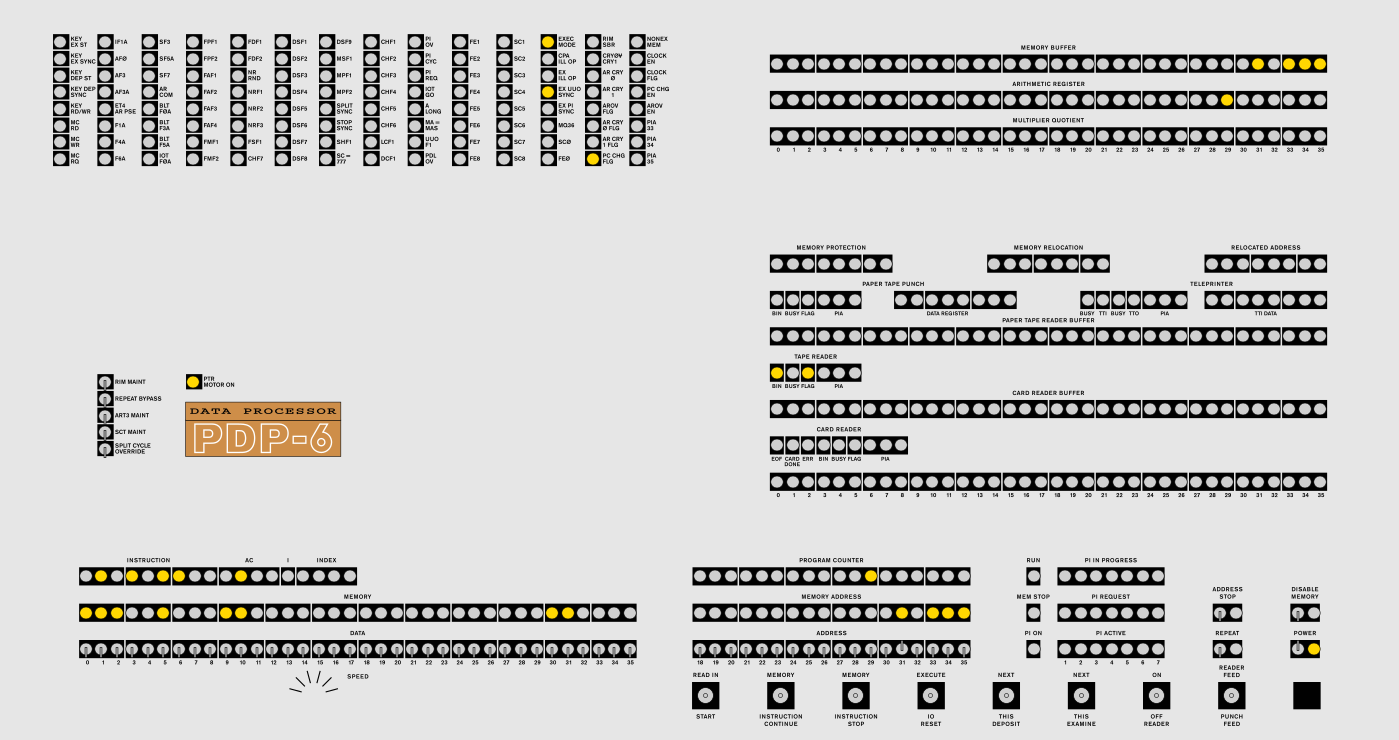
Both are driven by a virtual front panel but the plan is to create
|
|
a replica of the original panel.
|
|
|
|
The maintenance manual has flow charts, schematics and explanations:
|
|
[Volume1](http://bitsavers.trailing-edge.com/pdf/dec/pdp6/F-67_166instrManVol1_Sep65.pdf)
|
|
[Volume2](http://bitsavers.trailing-edge.com/pdf/dec/pdp6/F-67_166instrManVol2_Sep65.pdf)
|
|
|
|
|
|
|
|
## C Emulator
|
|
|
|
The code is more or less a transcription of the schematics into C.
|
|
This means you will not understand it unless you're familiar with the maintenance manual.
|
|
Pulses are represented as functions, when a pulse triggers another pulse
|
|
it does so by the `nextpulse` function which adds a pulse to the list of next pulses.
|
|
In the main cpu loop the list of current pulses is iterated and each pulse is called,
|
|
then (after checking some external signals) the current and next pulse lists are swapped
|
|
and the process begins anew.
|
|
The timing was not accurately modeled and there is room for improvement.
|
|
Due to the inexact timing the hardware connections (through the memory and IO bus)
|
|
were not implemented too accurately. This may change in the future.
|
|
|
|
### Building
|
|
|
|
The supplied makefile assumes gcc (there are flags to silence some stupid warnings).
|
|
Otherwise you need SDL and pthread.
|
|
|
|
### Running
|
|
|
|
The cpu (apr), console tty and paper tape/punch are implemented.
|
|
There are no other external devices yet.
|
|
The only things missing from the cpu is the repeat key mechanism.
|
|
|
|
## Verilog Simulation
|
|
|
|
The verilog code is a very accurate transcription of the schematics as well.
|
|
Since the real machine is asynchronous I had to pull some tricks to make it
|
|
work on an FPGA.
|
|
The real machine uses delays that are triggered by pulses and output another
|
|
pulse after some time. Instead of pulses I use clock enables, and delays are
|
|
implemented by a counter synchronized to the 100MHz system clock.
|
|
|
|
### FPGA
|
|
|
|
My FPGA board is a Terasic Cyclone V GX Starter Kit.
|
|
Communication with the virtual front panel is done over I²C via
|
|
GPIO pins 2 (SCL) and 3 (SDA).
|
|
The board's SRAM can also be read and written over I²C.
|
|
The TTY is connected to UART over GPIO pins 4 (RX) and 5 (TX)
|
|
|
|
## File tree
|
|
|
|
* `emu` source for the emulator
|
|
* `verilog` source for the verilog simulation
|
|
* `art` everything graphical
|
|
* `code` some test code for the PDP-6
|
|
* `panel6` virtual panel for the FPGA
|
|
* `tools` tools like an assembler and linker
|
|
* `misc` some misc. and old stuff
|
|
|
|
## To do
|
|
|
|
- repeat and maint. switches
|
|
- test thoroughly!
|
|
- devices (test UT, implement 340)
|
|
- timing
|